APEC 2017 – High-Q Resonator with Integrated Capacitance for Resonant Power Conversion

At APEC 2017, we presented a high-Q resonator with a multi-layer winding and integrated capacitance for resonant power conversion.

A low-loss inductor winding for MHz frequencies can be built by connecting in parallel multiple layers of foil conductors much thinner than a skin depth. To ensure  approximately equal current sharing among layers, a capacitance can be inserted into each layer as shown in the figure; this is similar to twisting the litz wire for equal current sharing among wire strands. This capacitance can also be used for resonance, which eliminates the need for additional lumped capacitors and connection between capacitor and inductor.

We developed a method to implement this multi-layer winding by using copper laminated on polyimide substrates for ease of handling. The orientation of copper layers adjacent to the polyimide substrate ensures that there is no significant electric field, and hence low effective loss, in polyimide. The required capacitance for each layer is provided by free-standing PTFE films. The prototype of this resonator at around 8 MHz have a quality factor around 830 in under 15 cm3, 50% higher quality factor than an inductor with a single-layer thick foil winding connected to low-loss ceramic capacitors.

For more details, check out our paper on IEEEXplore (pdf) and slides.

A Step-by-Step Guide to Extracting Winding Resistance from an Impedance Measurment

At APEC 2017, Benedict Foo presented a method for extracting winding resistance from an impedance measurement.  For details on this method see the paper.

Impedance analyzer measurements can be helpful in assessing inductor a  transformer winding resistance and predicting winding loss, but the measured ESR does not directly correspond to winding resistance. Neglecting the effects of core loss and winding capacitance can yield significant errors in the prediction. A step-by-step method to account for such effects and extract winding resistance from an impedance measurement is described. The proposed methodology is applicable to both inductors and multi-winding transformers. Several measurements are needed in this method; one is to determine the effects of core loss and the others yield the impedance from which winding resistance is extracted to form a resistance matrix. The winding resistance of a transformer was determined experimentally and the interactions between the winding resistance, effects of core loss, winding capacitance and inductance and their contributions to the measured impedance are demonstrated.

APEC 2017 Core Loss Presentation

At the APEC 2017 magnetics industry session on Tuesday morning, I presented a talk that included:

  • A brief summary of the PSMA/PELS Magnetics Workshop held the Saturday before.
  • A discussion of core geometry and dimensional effects in ferrite cores.
  • A discussion of different approaches to analyzing the effect of waveform shape on core loss.
  • A few tidbits on core and winding modeling.

The slides are available here.

2017 PSMA/PELS Magnetics Workshop Presentations

I gave two presentations at the PSMA 2017 Magnetics Workshop.  Brief summaries and slides are below.

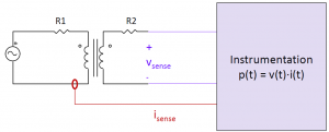
Two-winding electrical core loss test setup.

The first was an introduction to core loss testing, and a survey of basic and advanced methods.  Here are the slides: Survey of Core Loss Test Methods

It includes brief discussions of calorimetric methods and resonant methods.  Calorimetric methods can be tedious, but are valuable as an independent check on other measurements.  Resonant methods can improve accuracy at high-frequencies.

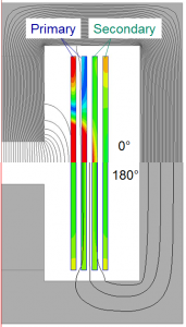
A simple 2:2 foil-winding transformer with current density and flux lines shown. In the top half, these are shown with the two windings excited with the same current, in phase. In the bottom half, they are 180 degrees out of phase. The losses are different by a factor of 4.

The second was a brief overview of magnetics modelling methods, including core and winding losses.  The slides include a list of key references at the end.

As one example of what’s in the presentation, there’s an explanation of why it’s not adequate to model transformer winding loss with two frequency-dependent ac resistance values.  As shown in this figure, the losses depend on the phase between the currents in the two windings, not just on their individual amplitudes.  A model that correctly includes all the interactions between the windings is a resistance matrix.

Methods of finding the resistance matrix are discussed in the presentation and detailed in the references listed at the end.