APEC Industry Session Presentation

Here are the slides from my presentation at the APEC magnetics industry session.

Industry session sullivan 2018.pdf

They provide an overview of the topics at the PSMA/IEEE PELS saturday magnetics workshop, focusing on dimensional effects in core loss and fringing effects.

I skipped over discussion of core loss with non-sinusoidal waveforms, because that was discussed in last year’s talk  and a previous presentation providing an overview of different methods.

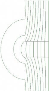
Fringing Effects

Our second presentation at the PSMA/IEEE PELS workshop on magnetics was on fringing, including:

  • The effect of fringing on gap reluctance,
  • The effect of fringing on core loss in laminated and tape-wound cores
  • The effect of fringing on winding loss

Here are the Fringing Effects Presentation Slides including references at the end.

Core loss: What we know and what we don’t know.

There’s a lot we know about magnetic core loss, and at lot we don’t know.  The situation is summarized in presentation slides from my presentation at the PSMA/IEEE Magnetics Workshop.  The slides have the references added at the end with reference numbers sprinkled through.

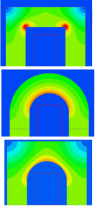
People were intrigued by the three simple flux crowding simulations shown here.  These aren’t intended to be highly accurate–they are based on constant permeability, and as pointed out by Bruce Carsten, the real behavior is nonlinear.  But the results are still interesting and somewhat surprising.  Based on loss proportional the flux density raised to the 2.5 power, the second picture–the circular hoop–doesn’t reduce loss as you might expect.  Rather, it raises loss by about 3%, compared to the simple square corners at the top.  But the bottom design does reduce loss, by about 8%, compared to the simple square corners.


High-Frequency Passive Components: a critical challenge for power electronics

Here are the slides from my talk today at G2ELab in Grenoble.

Discussion of modeling winding and core loss, designs for kHz frequencies, designs and challenges for MHz frequencies, and new approaches to passive components for MHz frequencies.  It includes a list of several dozen references at the end, and many of the slides include references numbers, so this can be a good entry point for finding more information on those topics.

APEC 2017 Core Loss Presentation

At the APEC 2017 magnetics industry session on Tuesday morning, I presented a talk that included:

  • A brief summary of the PSMA/PELS Magnetics Workshop held the Saturday before.
  • A discussion of core geometry and dimensional effects in ferrite cores.
  • A discussion of different approaches to analyzing the effect of waveform shape on core loss.
  • A few tidbits on core and winding modeling.

The slides are available here.

2017 PSMA/PELS Magnetics Workshop Presentations

I gave two presentations at the PSMA 2017 Magnetics Workshop.  Brief summaries and slides are below.

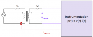
Two-winding electrical core loss test setup.

The first was an introduction to core loss testing, and a survey of basic and advanced methods.  Here are the slides: Survey of Core Loss Test Methods

It includes brief discussions of calorimetric methods and resonant methods.  Calorimetric methods can be tedious, but are valuable as an independent check on other measurements.  Resonant methods can improve accuracy at high-frequencies.

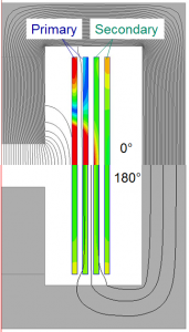
A simple 2:2 foil-winding transformer with current density and flux lines shown. In the top half, these are shown with the two windings excited with the same current, in phase. In the bottom half, they are 180 degrees out of phase. The losses are different by a factor of 4.

The second was a brief overview of magnetics modelling methods, including core and winding losses.  The slides include a list of key references at the end.

As one example of what’s in the presentation, there’s an explanation of why it’s not adequate to model transformer winding loss with two frequency-dependent ac resistance values.  As shown in this figure, the losses depend on the phase between the currents in the two windings, not just on their individual amplitudes.  A model that correctly includes all the interactions between the windings is a resistance matrix.

Methods of finding the resistance matrix are discussed in the presentation and detailed in the references listed at the end.


Simplified litz wire design

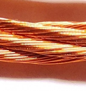
125-strand litz wire (5x25)

125-strand litz wire (5×25)

We’ve published a lot of papers on litz wire. Their emphasis has been academic, reporting new optimization results and calculation techniques.  But they are are often too complex for design work, for an engineer who has many different issues to deal with.  With that in mind, we took a different approach in a paper presented at APEC 2014, focusing on making the simplest possible design method that would still provide good practical guidance of litz wire design.  We found a way to incorporate the results of some of our more sophisticated analysis into simple formulas that can be quickly and easily calculated in a spreadsheet or the like, so that you can get good recommendation for litz designs very easily.
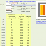
Illustration of the main page of the spreadsheet you can download.

Spreadsheet main page

The full paper is available on our web site.  The first two pages are all you need to read to get complete instructions on the method.  To demonstrate how easy it is to use in a spreadsheet, here is the method implemented in a spreadsheet.  You only need to put in four numbers–frequency, number of turns, core window breadth and turn length–and you get a range of options with the performance of each listed.

The simplest calculation is for a transformer winding, but the paper and the spreadsheet also include calculations for gapped inductors, accounting for the field in the region of the gap.  Similarly the base method is for sinusoidal currents, but both include an easy adjustment to deal with nonsinusoidal waveforms.

There are some situations that this method can’t deal with–for example, if you have an unusual geometry, or multiple windings with different current waveforms in each winding.  In those cases, our online LitzOpt calculator (which has recently been updated to be a little more robust and user friendly) can address most situations directly, or pretty much any situation in combination with an external field simulation.

In addition to being easier to use, the new method also features a calculation that helps you choose some of the details of the wire construction–how many strands are twisted together in each step.  Typically one might combine somewhere between 7 and 50 strands in the first step, and then twist several of those bunches together in the second step, etc.  The details of this sequence affect how well the wire eliminates skin effect. The later twisting steps should never combine more than 5 bundles together, but it’s often OK combine many 10s of strands in the first step.  The new calculations tell you how many it’s OK to combine in that first step.

Another choice in the construction is the pitch of twisting at each step.  This paper and spreadsheet don’t provide any guidance on that, but we are publishing a new paper on that topic at COMPEL 2014.  That paper will appear here soon after the conference.

T

High-frequency core and winding loss IEMDC plenary

copy of the slides from this IEDMC plenary presentation is now available, with references for each topic added.

This presentation includes information on:

  • When high-frequency loss effects become important in windings.
  • Alternatives for modeling and optimizing windings, and when they apply.
  • Alternatives for modeling core losses.

The information is from work in the field of inductor and transformer design for power electronics, and is targeted at a machine design audience, but is useful for high-frequency power transformer and inductor design as well.

Here is a pdf of the slides with references.


Tesla Tech Fair Press and Photos

nine

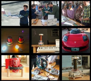
Nine different exhibits featured at the Tesla Tech Fair

The Tesla Tech Fair on April 4th was a great success.  It featured panelists David Perreault and W. Bernard Carlson, author of Telsa, Inventor of the Electrical Age, which wasn’t available at the time of the event but is now available.  It also featured nine different exhibits from Thayer and MIT students, staff and faculty.

The event got written up in The Dartmouth and The Valley News.  There are collections of photos on Flickr from Thayer and from the Hop.  The oneTesla team wrote a blog post about it as well.

Thanks to everyone who made this a success, including the Hopkins Center for the Arts and Thayer School of Engineering. The event was supported by the Office of the President and the Office of the Provost as part of Dartmouth’s Year of the Arts initiative.


Tesla TechFair

Thayer School of Engineering and the Hopkins Center are celebrating Nikola Tesla this spring, in conjunction with Tesla in New York, an opera by filmmaker Jim Jarmusch & composer Phil Kline.  Thayer will host a Tesla TechFair, including a panel discussion and demonstrations, on Thursday, April 4, 2013, 4:00-6:00 PM.

Dartmouth students are invited to build and/or demonstrate a Tesla-related technology—something he developed, invented, pioneered, or patented, or the modern application thereof.  The demonstration should be interesting to engineers and non-engineers alike. Think remote control helicopters, Tesla coils, wireless chargers and death rays (just kidding: don’t kill anyone).  Selected proposals will receive up to $500 for materials and supplies.  Proposals are due March 8.

Need Inspiration?

Here’s a selection of Tesla inventions and their modern applications:

For full details and an application form, here’s the call for entries.